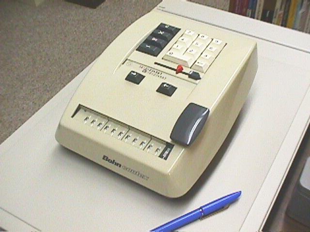
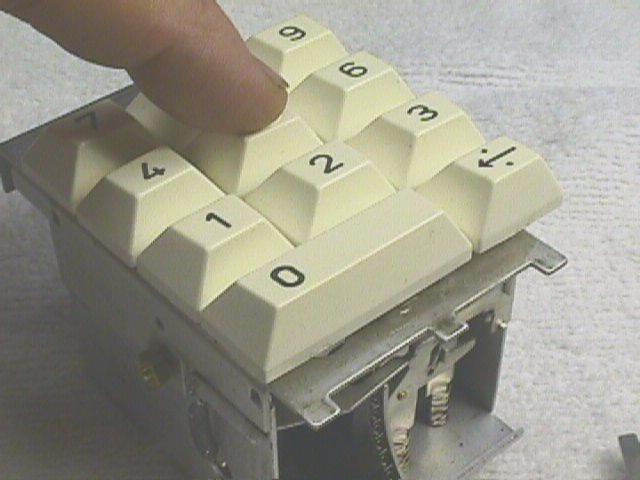
The Bohn Contex is a simple 10-key mechanical calculator produced in Denmark by Brdr. Carlsen A/S in Birkerod, Denmark. I have a model 10, which was probably made in the late 1950's.This page describes the process I used to repair my machine. I hope it will be useful to others who care for this historic calculator.
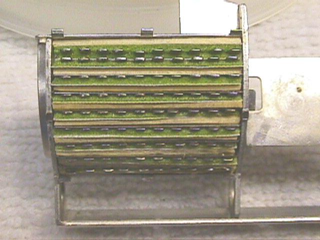
The Contex machines are quite simple and are frequently found in working condition. Unfortunately, mine arrived with a serious problem. The 10-key function is implemented by a matrix of pins that shift to the left as digits are entered. The pins pass through a curved aluminum box where they are retained by what appears to be a mass of synthetic sponge material. In my machine, the sponge had decayed, causing the pins to be loose. During normal operation, some pins would extend or retract by themselves, introducing more or less random numbers.
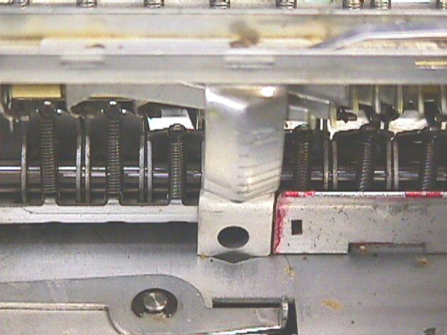
The main push down button for adding must be removed so the cover will come off.The cover is held by two screws on the right and left edge.
Be careful not to loose the small red shift indicator which will pop off when you lift the cover.
The keypad assembly is attached with one screw on the back upper edge. It has a lever that engages a slot on the right side of the frame. The front of the keypad has a hook that locks the sliding pin matrix. You have to raise this hook to remove the key pad. On the left side of the keypad assembly you will see a tab held by a coil spring. Press down on this tab to release the locking hook as you pull backwards and up to remove the keypad. You may want to shift the matrix all the way to the right to help the hook disengage.
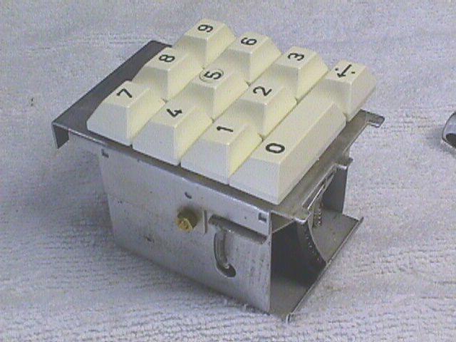
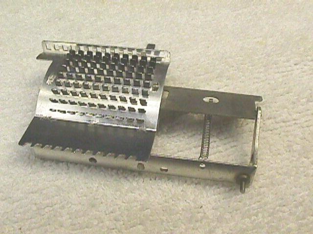
The keypad box removed.
Keypad front showing matrix locking hook.
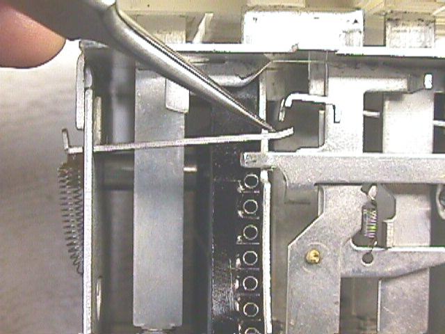
The pin matrix has a row of holes on the top edge which you can now see clearly. Examine the front side of the keypad and note the locking lever you raised by pressing the tab on the left side of the keypad box. This will help you understand what has to happen when you replace the keypad.The matrix slides along a rod that passes through the bottom edge. The rod is held in place by two snap rings: One on the outside and one on the inside. You will need to remove the main spring to reach the outer snap ring. The hook for the main spring at the front of the frame is held in place by the spring tension. Keep track of it when it falls out. After removing the outside snap ring, you can slide off a plain washer, a wave washer and the locking leaver.
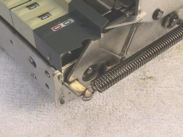
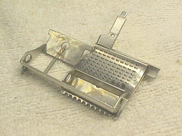
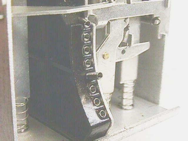
The main spring hook.Inside the frame, the rod passes though a crank-like casting, another snap ring and a nylon spacer. Pull off the snap ring and you can slide the rod out from the left side of the machine. Pay attention to the fork-like lever that extends forward from the control key cluster. This fork must straddle the rod when you assemble the machine. Also note the lever that engages a small pin on the bottom edge of the matrix. This lever supplies the spring force that forces the matrix to slide leftward as numbers are entered.
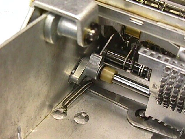
Inner attachments on pin matrix slide rod.
Pulling out the slide rod.
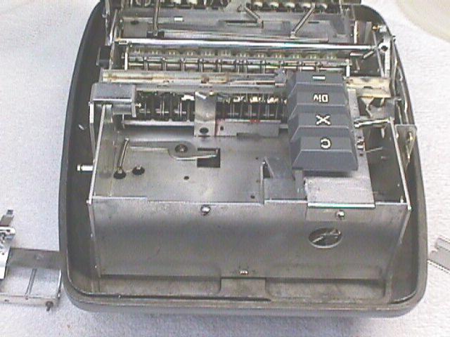
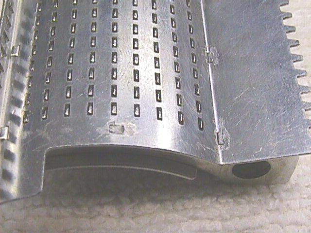
Case with matrix and keyboard removed.
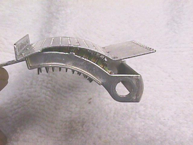
Pin matrix "cover" side. (Faces back of machine)
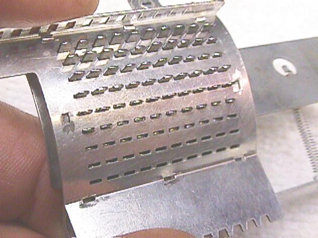
Pin matrix "back" side. (Faces front of machine)The pin matrix is not designed for easy repair. It is staked together by some kind of punch that deforms tabs that extend through the cover. The "cover" is the convex side of the matrix with holes for the tabs.
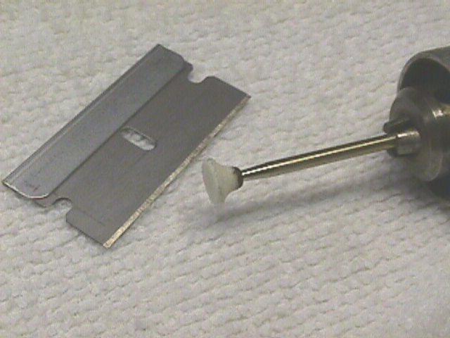
The grinding burr.I used a very small grinding burr in a flex-shaft tool to grind off the expanded part of each tab. The pictures show the details. After grinding the tabs flush with the cover's surface, you can pry off the lid. Be very careful and pry only near each tab, working around the edges slowly to avoid bending the cover.
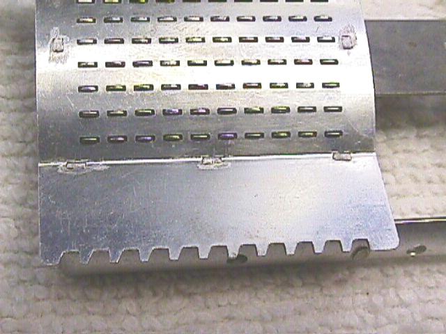
Bottom edge showing ground-off tabs.
Side tab after grinding.Inside you will rows of pins sepated by layers of foam and small metal shims. Dump everything out and clean up the dried adhesive on all parts. I found that it took a fairly powerful solvent to deal with the dried glue. I tried alcohol & electrical contact cleaner with no effect. Orange peel extract worked slowly. Carburator cleaner worked rather well.
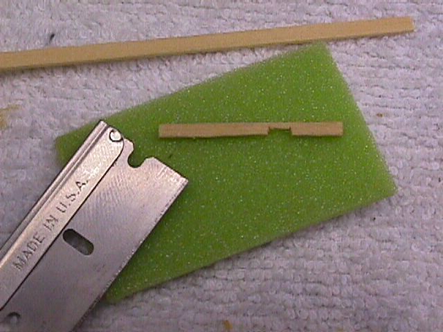
I needed some kind of dense but soft foam that would grip the pins. I tried cutting up sponges and other household objects, but it was too difficult to recut these materials into the uniform thin layers required. I finally found the perfect foam in the padded cover for our dining room table.

"You want a piece of the dining room table cover?"This was a thin green foam with a white plastic backing. The backing makes it easy to cut into thin rectangles that fit the pin matix box. Unfortunately, it is too thin even when combined with the original metal shims. I cut some wooden cocktail swizzle sticks to pack the extra space. Finding a thicker foam pad might be better.
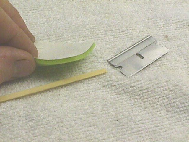
Spacer materials
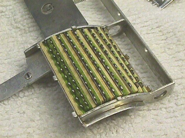
Interior of pin matrix after rebuilding
The "odd" space is under the first row.An important point: The foam strips and spacers must not bind against the sides of the box. If they do, waves will form and allow some pins to slide freely. I discovered this after assembling my machine for testing, so save youself some time and make sure all the pins are held so they slide with some resistance.
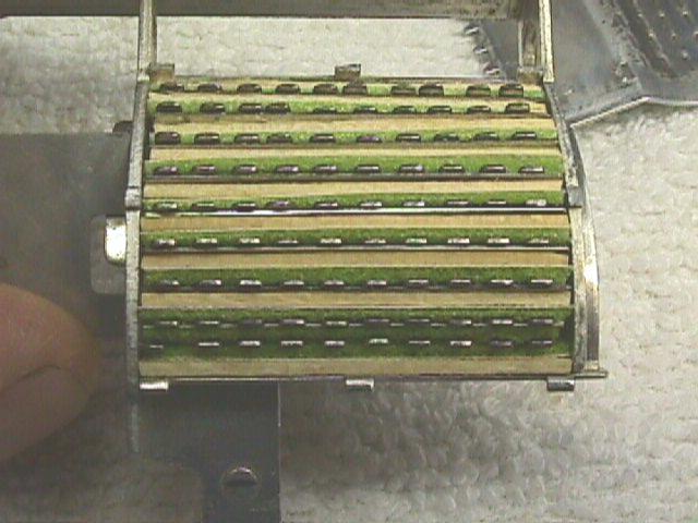
You will note that there are only seven metal spacers for 8 gaps between the rows. Each row requires a strip of foam held agains the pins by some solid backing. The upper and lower row can be packed with a layer of foam against the top and bottom of the box, so they don't need the metal spacers. Starting at the bottom, each row gets one spacer and one foam strip until you get to the second row from from the top. Nothing is required in this gap because the upper row is going to rub against the foam between the pins and the top of the box. I put in a layer here anyway to make the rows line up better during assembly. The wooden spacer at the top edge must be cut to clear a tab on the indicator/clearing arm.
Cut-out on upper spacerFor my rebuild, the top and bottom edges got two wooden spacers and a layer of foam. All the inner rows got one metal spacer, one wooden spacer and one layer of foam.
Make sure nothing sticks out above the rim!
Now hook the cover over the curved tabs on the top edge and close it down as far as it will go. Move the pins with your fingers while pressing gently down on the cover. It is very easy to line up the pins so that whole rows drop into place at a time. Snap the cover down over the tabs and make sure there is no gap along any edge.
Closing the cover, edge view.
Closing the cover, top viewMy cover fit so tightly that it was probably unnecessary to fasten it any further, but I used a spring-loaded center punch to make a divot in the head of each tab. Be sure you test all the pins before doing this step: Push all the pins through one side and shake the box or tap it against the table top. The pins should all remain extended. Push the pins through to the other side and repeat the test. Try sliding each pin with tweezers and make sure you feel a uniform drag. If any row seems loose, open the box and add another spacer.
The process is a simple reversal of the disassembly steps. I forgot that the fork on the operation key cluster has to straddle the pin matrix slide rod. If you forget this step, the machine will work perfectly except that during division, the adding lever will not be automatically blocked before you shift. Also take care to engage the sping lever fork with the pin on the bottom of the pin matrix. The most difficult step is inserting the keypad box. The locking hook must be held open to engage the row of holes on top of the pin matrix. Simultainiously, the locking lever on the right side must pass though the right side of the frame.
When a number is entered on the keypad, a spring pusher extends from the front side of the keypad box. This pusher extends a pin on the matrix towards the front of the machine.
Pressing the five key: Top and front view.
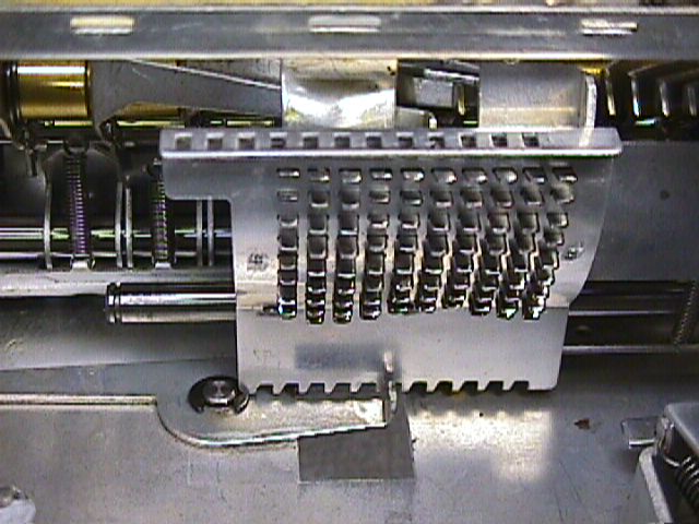
A row of levers are arranged in front of the pin matrix. The levers are pivoted on a rod. When the adding bar is pressed, each lever pivots downward, sweeping across the concave face of the pin matix. The lever will stop when it hits an extended pin. The front of each lever is a gear-sector that incrementally rotates the result register.
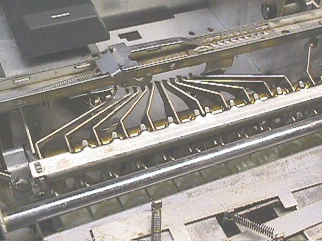
The matrix pin sensing levers.
Gear sectors in the upper-most "Nine" position.When the indicator arm with the red pointer on top is used to clear the machine, the pin matrix slides by a curved bar. This presses all the pins back into the matrix.
The pin matrix reset bar.Addition
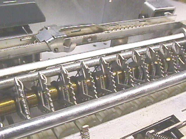
When the adding bar is pressed, the levers descend until they hit the pin matrix pins. As the adding bar goes back up, crown-gears on the counting register drive shafts are shifted forward to engage the sector teeth. As the sectors return to their home postion, they rotate the crown gears.Subtraction
When the subtraction key is pressed, the entire result register assembly shifts to the left. When the crown wheel gears slide forward to engage the sector teeth, they engage on the right edges instead of the left edges. The sectors will then rotate the crown wheels in the opposite direction.
Multiplication
When the multiply key is locked down, the pin matrix does not automatically side to the right (clearing the pins) when the adding lever is released. The number in the pin matrix remains, so the operator can now shift the matrix leftward and perform multiple adding cycles.
Division
This is the most interesting operation. As with multiplication, the automatic clearing function is disabled. The subtraction key is also locked down. When the result register shifts left to subtract, a locking tab extends from the right edge. This will lock the adding lever when the result register shifts back to the right. When the result register underflows to a negative number, the subtraction key pops up automatically. The next cycle will add back the value that caused the underflow. The result register shifts right to perform the addition and this engages the locking tab. When the operator presses the shift-right key, the subtraction key is locked down again. The result register will shift left, unblocking the adding lever.
Links
Consise Instructions
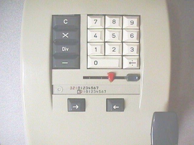
From the instruction plate on the bottom of the machine.How to use the decimal indicator
This is the transparent slider under the red arrow.How to perform continued multiplication
How to multiply any number of factors without clearing the machine.The Old Calculator Web Museum
This site is a gold mine. The principle of operation and history are discussed at this link.An original advertisment
This is also a link into The Old Calculator Web MuseumErnie Jorgenson's Office Machine Americana
All kinds of office machine information and copies of original manuals.The Swedish Typewriter Page
You will have to dig around on this site to find the Contex information.The Museum of HP Calculators
Also has articles on the history and operation of mechanical calculators.Museum of Soviet Calculators on the Web
The "Bystritsa" was a copy of the electric Contex-30.X Number World of Calculators
This page has opeator instructions which also apply to the mechanical version.
Includes the "Brief History of Mechanical Calculators".The csparks home page
Has information on the early Contex machines.
"There appear to be two different machines within the "Contex 10" label. One type has a dark grey plastic body and the serial number again of nine digits but starting with "431". The second type is of a lighter grey, has a slightly different register presentation and the serial number commencing with "434". A former serviceman on the Contex machines confirms the existence of an upgraded model 10, identifiable by the plastic colour."
My other obsessions and contact information.