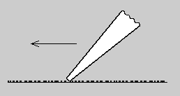
Figure 1: Pushing a screwdriver across sandpaper
Richard Thoen
Version 1.0, February 24, 2004
The cycloidal tooth has been outmoded for quite awhile. As George Grant put it in his book: A Treatise on Gear Wheels, first published in 1890:
The cycloidal tooth would never be missed if it were dropped altogether. But it was first in the field, ...has the recommendation of many well-meaning teachers, and holds its position by means of "human inertia," or the natural reluctance of the average human mind to adopt a change, particularly a change for the better.
A prophetic statement, for within a decade the fledgling automobile industry had dropped the cycloidal tooth. A classic instance of the firmly entrenched practice being at odds with a new set of circumstances.
A quirk of the cycloidal tooth is that it develops a tooth-to-tooth turning error as the operating center distance deviates from the nominal center distance. Another problem is the relatively large profile error, stemming from errors encountered when laying out and machining the cutter (hob) profile -- a curve with changing radius of curvature. Automobile designers dropped the cycloidal tooth when they found that these errors produced audible whine and high wear. The involute tooth prevailed because its motion is independent of center distance variation, and its hob profile is essentially straight-sided.
Clock designers, however, were not about to drop the cycloidal tooth. It had served them well for centuries, and for them there had been no change in circumstances. In clocks, the speeds are low and loads are light, so noise and wear are not significant. Besides, at that time (circa 1900), there was no way of calculating the center distance for involute pinions with low numbers of teeth. It would have been necessary to construct large tooth layouts -- a complex construction which is not very accurate.
Automobile designers had it easy, because on their pinions the tooth numbers were such (18 or more) that standard tooth proportions could be used. That is, tooth thickness was half a circular pitch at the standard pitch radius, so center distance was simply the sum of nominal pitch radii.
Clock designers, however, could not use standard tooth proportions, because on their pinions the tooth numbers were such (as few as 6) that the teeth would be undercut if the thickness were half a circular pitch. (Undercut will be discussed later, in connection with Fig. 2.) Further, to avoid undercut they would have had to contend with pointed teeth, and it wasn't until the mid-20's -- when Professor Earle Buckingham invented the involute function -- that nonstandard center distance, and radius at which teeth point, could be calculated. (The involute function is defined as inv(φ) = tan(φ) - φ, where inv(φ) is given and φ is unknown. Until the advent of the computer, φ was found from a table. Nowadays, φ can be found via Newton's Method on a $30 handheld calculator.)
The involute function cleared the way for the clock industry to capitalize on the manufacturing and inspection advantages inherent to involute gearing. In particular, the manufacturing method for involute gearing is much more accurate than that for cycloidal gearing, because, as noted above, the hob profile for involute gearing is essentially straight-sided, whereas for cycloidal gearing the hob profile is a curve with changing radius of curvature. And the inspection method for involute gearing is at least ten times more accurate than that for cycloidal gearing, because involute gearing can be checked on a gear roll tester, whereas cycloidal gearing must be checked on an optical projector. Specifically, a gear roll tester can easily detect a profile error of 0.00005 inches, whereas an optical projector might not detect 0.0005 inches. For example, in trouble shooting a set of involute gears I couldn't detect any error on an optical projector, but for the same set on a gear roll tester I measured 0.0015 inch tooth-to- tooth composite error, which corresponds to about 0.001 inch profile error.
The 0.0005 inch error in optical projection is well known. For instance, an American gear standard reads: "Profile errors less than 0.0005 inches cannot readily be detected by projection." And since the bilateral profile tolerance for cycloidal gearing is typically 0.0005 to 0.00025 inches, the inspection error is 100 to 200% of the tolerance, or far greater than the generally accepted figure of 10%. This inspection deficiency obviously contributes to variation in fuse performance from one production run to the next, as evidenced by the fact that inspection data for cycloidal gearing often give no clue as to the cause of variance. Moreover, this inspection deficiency means that the timeout tolerance for a fuse with cycloidal gearing will always be greater than that with involute gearing, for the simple reason that the backlash for cycloidal gearing cannot be held as close as that for involute gearing.
Thus, with the arrival of the involute function in the mid-20's the clock designers should have jumped at the opportunity to switch over to involute gearing. But the fact of the matter is they didn't budge. Resistance to change is characteristic of well established industry, even when faced with extinction. For instance, neither Keuffel & Esser (slide rules) nor Friden (mechanical calculators) made the transition to handheld calculators. And currently the American auto, steel and textile industries are resisting change, via protective tariffs, import quotas and federal handouts.
As so often happens, change came from outside the system. During World War II,
for example, Louis Martin -- Chairman of the American Gear Manufacturers
Association (AGMA) Fine-Pitch Gearing Committee from its inception in 1941
until 1953, secretary or member of several other AGMA committees, holder of 22
patents and author of scores of articles and papers -- proposed replacing the
troublesome cycloidal gearing in the FM45 fuse with involute gearing. He knew
a thing or two about timers, because he was working at Kodak, and the timer
in the Kodak camera used involute gearing to drive a runaway escapement.
In his words:
The "big wheels" at (Picatinny Arsenal) were adamant and would not permit
deviations from the drawings of that era, 1940. They maintained that these
gears had been made before so why couldn't Kodak make them? Of course they
had, with non-generating milling cutters. We had a war to win and wanted to
mass produce these items (with conventional generating cutters) . ... Millions
of dollars could have been saved and much better fuses been made if it had not
been for the asinine, arbitrary decisions of those who didn't know the "score."
At one time I spent 300 hours making enlarged metal templates of the diverse
gears in the FM45 train . ...My tooth form was completely interchangeable
with... the existing cycloid. Came the day when the fuse Committee met at
Kodak for a regional conference, which occurred bimonthly. They came to my
department -- the whole galaxy of "brains." I showed them my templates mounted
on a big board about 5 x 10 feet. ...The brown plastic templates were cycloids
and the steel ones involute. They toyed with these templates for a few minutes,
...and then walked away nonchalantly. My heart sank. George Ensign, Master
Mechanic at Elgin National Watch, stayed behind ... and really got into the
problem. ...When he left he said, "Lou, I am sorry for you, but what can you
do with those S.O.B.'s? They might as well be working for Hitler."
But Martin didn't give up. In 1956, at a Picatinny Arsenal fuse symposium, he described an experiment wherein he took a production fuse with a tuned escapement and simply replaced the cycloidal gearing with involute gearing. Contrary to conventional wisdom, he found involute gearing to be more efficient than cycloidal gearing.
In 1962, Frankford Arsenal conducted a similar experiment, again by taking a production fuse with a tuned escapement and simply replacing the cycloidal gearing with involute gearing. This time I supplied the involute gearing (150 sets), based on a tooth form I had developed for miniaturized servomechanisms. (See Enlarged-Tooth Pinions in Appendix.) Frankford Arsenal reported no significant difference between cycloidal gearing and my form of involute gearing, but made no effort to switch over to involute gearing.
In 1964, Honeywell began to use my form of involute gearing. It started with gears I had designed for a fuse that required close tolerances, namely, tolerances corresponding to hobbed gearing and jig-bored plates. In the next few years a procession of engineers from other fuse projects began to call on me, to discuss malfunctions. What happened is that they had copied my basic gear data, ignored the tolerances, and gone over to die cast gearing and stamped plates. And in so doing they had violated the cardinal requirement of gearing -- overlapping tooth contact. Specifically, each fuse had an 8-tooth, 100 diametrical pitch pinion. For close tolerances the tooth contact overlapped, but for tolerances corresponding to die cast gearing and stamped plates the tip of the pinion could gouge the dedendum of the driving gear. I was able to get one of the project engineers to check his contact ratios. He found them to be as low as 0.6. (Gouging occurs whenever the contact ratio is less than 1.0.) This 0.6 figure, incidentally, can be read from the 0.08 curve in Optimum Tooth Numbers for Small Pinions. (See Appendix.)
Even so, this pinion was used in the M588, M739, M587, M724 and XM41 fuses. The M739, for example, was produced in very large quantities, perhaps a million or more, but to get it to work it was necessary to use an exotic dry-film bonded lubricant, to offset the effect of tip gouging. The point of all this is that my form of involute gearing survived the gauntlet of military-industrial bureaucracy, in which the inevitable conflicts between budget, schedule and design are resolved by sacrificing the design.
In 1971, I was called in to redesign the XM41 fuse. About 10,000 were subsequently produced, using conventional lubricant. Then, about a year later it was adapted to a radiosonde, in which it flew without any lubricant at all.
In 1972, in response to Naval Ordnance Lab rejecting my form of involute gearing, I evaluated the static efficiency of involute and cycloidal gear trains, by removing the escapements from various production fuses and measuring the input-output torques. I found my form of involute gearing to be more efficient than cycloidal gearing.
In 1980, the Copperhead fuse went into production, using my form of involute gearing. In reviewing the prints for Picatinny Arsenal, I found gross errors in the gear data, including outright interferences. (About a year later, at a tool show where Copperhead parts were on display, a vendor told me that he had to remake the sector tooling, because of an interference between the sector tip and pinion root.) Actually, the design is such a mess that it's not possible to make the gears to print. (Two different vendors have encountered this problem, but nothing has been done about it.) Nevertheless, upwards of 20,000 fuses have been produced. Just another example of my form of involute gearing surviving the gauntlet of military-industrial bureaucracy in which the inevitable conflicts between budget, schedule and design are resolved by sacrificing the design.
In the past decade the number of designers and manufacturers of cycloidal gearing has declined. Nearly all of the U.S. clockmakers have either gone out of business or stopped making mechanical timepieces. But amid this decline it has been business as usual for the non-clockmakers (the government contractors), whose design skills usually consist of copying gear data from old designs, a practice which ignores the fact that the original gear data was tailored to a particular set of tolerances and allowances. Worse yet, the non-clockmakers' vendors -- small gear shops, the counterpart of clockmakers' in-house gear departments -- are not really concerned about quality. They know that the optical projector is very forgiving, and are well aware that competition forces everybody to exploit the situation. Competitive mediocrity is the name of the game. In short, from the standpoint of a general mobilization, there is not an adequate industrial base for cycloidal gearing.
To this day however, cycloidal gearing has its advocates. They argue that tooth contact should not occur before the line of centers, because tooth action before the line of centers (approach action) is less efficient than tooth action after the line of centers (recess action). In other words, approach action is bad and recess action is good, and it follows that cycloidal gearing is better than involute gearing, because approach action is easier to avoid with cycloidal gearing.
This argument goes back a long way. For instance, from a book by Sereno Newton, published in 1832, we have:
The friction of teeth approaching the line of centres is much greater than in receding from it, ...for when a machine becomes worn it causes irregularity in its movements ...therefore the teeth ought, if possible, never begin to act before they arrive at the line of centers.
Sounds logical. Approach action is analogous to pushing the tip of a screwdriver across a sheet of sandpaper (Figure 1), whereas recess action is analogous to pulling. Across coarse grit sandpaper (e.g., #80), the screwdriver movement is very erratic for pushing, tending to gouge and dig in, whereas movement is uniform for pulling. But it is important to note that across fine grit (e.g., #600), movement is uniform for both pushing and pulling.
This analogy also explains why the cycloidal tooth is now passe. First it is important to acknowledge that the coefficient of friction for approach action cannot be different from that for recess action, for when Leonardo da Vinci slid weights across a table, observing that "Friction produces double the amount of effort if the weight be doubled," he didn't have to differentiate between pushing (approach) and pulling (recess). From this it becomes clear that early clockmakers were struggling with the consequence of geometric defects (surface irregularities, pitch errors, profile errors) and friction, namely, with a large difference between approach action and recess action (just as there is a large difference between pushing and pulling a screwdriver across coarse grit sandpaper). But times have changed. Geometric defects are now considerably smaller, which means that there is little difference between approach action and recess action (just as there is little difference between pushing and pulling a screwdriver across fine grit sandpaper), and in turn no justification for using the cycloidal tooth.
By 1890, George Grant, who had built the first hobbing machine a few years earlier, was pooh-poohing approach action, saying that it gave "little trouble when the teeth are properly shaped and cut."
By 1940, following a half-century of vast improvements in gear accuracy, A.L. Rawlings, in his book The Science of Clocks and Watches, ended his discussion of approach action with "So much for theory; but if you look at any cheap clock or watch you will find pinions (with approach action), and these all work quite satisfactorily."
By 1966, following another quarter-century of improvements in gear accuracy, many associated with analog computing mechanisms, George Michalec didn't so much as mention approach action in his 620-page book on fine pitch gearing, Precision Gearing: Theory and Practice.
Nowadays, although experimental evidence shows involute gearing to be more efficient than cycloidal gearing, conventional theory still indicates just the opposite. This theory, as proclaimed in textbooks, assumes that tooth and bearing losses are independent of each other, and that efficiency is independent of torque. But all this is an oversimplification, the most simple and striking evidence of which is the diametrically opposite results indicated by conventional and exact theories. Specifically, for an increase in center distance, conventional theory indicates an increase in efficiency, whereas exact theory indicates a decrease. Accordingly, tooth and bearing losses cannot be treated separately, gear train efficiency is a function of torque, and gear train efficiency is nearly independent of tooth type. (See Friction Loss in Small Journal Bearings in Appendix; specifically, Fig. 2 and last paragraph.)
Lastly, this historical diatribe should not be construed as saying that there is no longer a niche for the cycloidal tooth. There is -- in a science museum.
George Grant, A Treatise on Gear Wheels, Philadelphia Gear Works, 1890.
Earle Buckingham, Spur Gears, McGraw Hill, 1928.
Sereno Newton, I Can't find this book....
A.L. Rawlings, The Science of Clocks and Watches, Pitman, New York, 1944.
George Michalec, Precision Gearing: Theory and Practice, John Wiley, 1966.
I don't have these sections from Mr. Thoen yet, but when they arrive, they will appear here. - Editor.
UPDATE: I have these articles now. I just have to write up the web documents.
Enlarged-Tooth Pinions
Optimum Tooth Numbers for Small Pinions
Friction Loss in Small Journal Bearings