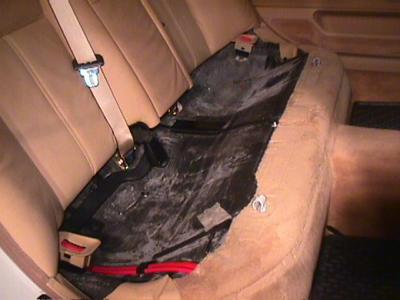
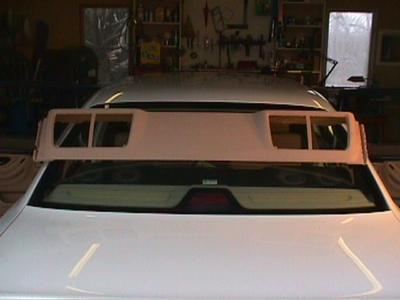
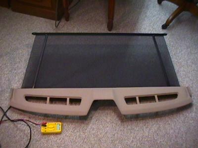
Rear set removed
Hugh Sparks
Version 1.0, March 28, 2003
"I'm surprised yours lasted so long. The mechanics hate them."
The rear power sun screen goes up and down, but when it goes down it makes an obnoxious "clack-clack-clacking" noise for about 10 seconds.
How it was designed to work
The motor is supposed to drive the screen up and down until the mechanism hits an internal stop. This simply stalls the motor, which continues to apply torque until a timer relay shuts off the power.
What goes wrong
Over the course of a few months or years, the drive fails because the forces involved in colliding with the stop destroy the inferior materials used to make the gears. (Plastic fiber and pot-metal.)
The car
This page covers the 1995 e38 (a 740 iL.) Probably many other model years are similar, but I did find significant differences between this car the and 735 covered on John Evan's sun screen repair page.
A fantasy
Owner:
(Calling BMW on the phone.) "I'm having a problem with my car,
and I've discovered that most customers who have this model are having
the same problem. May I speak to someone in engineering please?"
BMW:
"That's terrible news sir. I'll put you through to
the chief engineer." (10 minutes of over-seas phone-maze follow.)
Wolfgang:
"Ja?"
Owner:
"Did you design the rear power sun screen for the 7-series?"
Wolfgang:
"Ja, ich entwerfen d Sonnenschutzrollo. Sein nicht es gros?"
Owner:
"Well, actually I'm having a little problem with it. Also, could
you please speak English?"
Wolfgang:
"Still the English? You must be a new BMW owner! How can I help?"
Owner:
"The gears in the sunscreen drive fail rapidly. The fiber
worm gear or the pot-metal drive gear get chipped up when the motor stalls.
This causes the sun screen to fail in nearly every car."
Wolfgang: "Gut Gott, das nisht goot! Sorry. I mean: That's awful! I think we should have made those gears out of bronze! In such an expensive car, the cost of a small bronze gear is nothing. I'll call the factory tomorrow and put in an engineering change-order. We'll get this into production next week and recall the whole parts inventory from our dealers.
I'm really glad you brought this to our attention. That accessory has been in production for 10 years and no one said a word. All those customers suffering in silence... And deprived of my wunderbar sun screen... Oh The Humanity! Please let me send you one of the new gears."
Owner: "Gee, thanks! What a great company!"
Overview
Open the motor-drive gear case and fix the gears. The gear boxes fail in several ways, so there is no one-size-fits-all solution. You have to open the box and see what's wrong. Fortunately, there are several solutions that don't involve cutting new gears, although that would certainly be an economical possibility if you have a small machine shop.
Credit for part of this idea goes to John Evans, who has published a wonderful web page showing how he fixed his sun screen by rotating a bad gear to a new position. He has many other good ideas for 7-series owners.
It turned out that my gear box (and car) are a little different than Mr. Evan's. My gears were not as damaged so I didn't need to rotate them or saw out a section as he illustrates. Instead, I was able to alter the meshing depth and restore normal operation. Also, the direction of rotation to raise and lower the screen is opposite of that reported for the E32. This caused me to experience an unpleasantness when I opened the spring-loaded gear box following the E32 instructions.
As is often the case, most of the work was getting at the offending part. The following sections show every step in excruciating detail.
It takes about 1.5 hours to have the gear box open on your bench and about 1 hour to put the car back together. The time you will spend on the gear box is unpredictable, but my fix took about one hour of playing around before I decided what to do. After that, the repair took only 10 minutes.
I like a linear presentation of repair steps, but much of this material will be routine for the average BMW owner. Skip to the good stuff using the links below.
Simply pull up on the front edge, then pull forward and lift the seat out of the car.
The two seat backs and the center section are each attached at their bottom edges by a pair of tabs. Some have nuts and others have bolts that fit on studs. All are 10mm. The outer tabs on the seat backs are somewhat hard to see. They are oriented to bolt to the sides of the car. It is best to pull out the head rests before you detach the tabs.
Once the bolts are out, pull straight up on the seat backs and then pull out and away at the bottom edge.
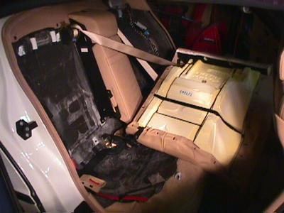
The center arm rest unit is removed in the same way: Pull up, then out at the bottom.
It isn't necessary to take the seat backs out of the car. They are trapped by the seat belts threading through them. Just put them on the floor in front of the rear seat.
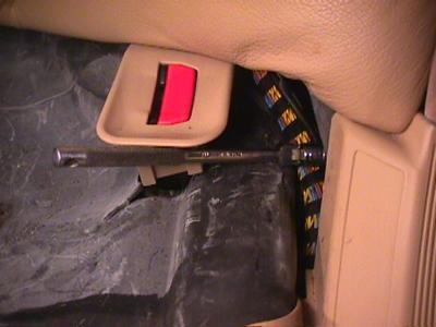
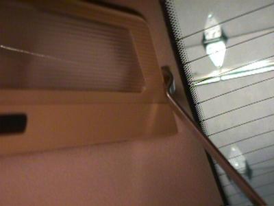
Next, remove each of the "C" pillar trim covers: First pry out the lamp housings. They are held at the top and sides by rounded springs. The bottom edge has a lip that hold it in the trim, so you can't pry on the bottom edge. Pry gently along the top edge. Swing the top edge outward, then pull up to disengage the bottom lip.
Inside the lamp area you will find 3 8mm screws. Remove these to free the pillar cover. The middle bolt is just out of sight on the upper edge shown in the photo below.
To remove the pillar cover, disengage the front edge from the door trim and then pull gently and slowly forward. The rear edge covers the fine wires for the in-glass radio antenna. If you pull roughly, you may break these wires.
As you remove the pillar trim, thread the lamp assembly through the hole and let it dangle by it's wire.
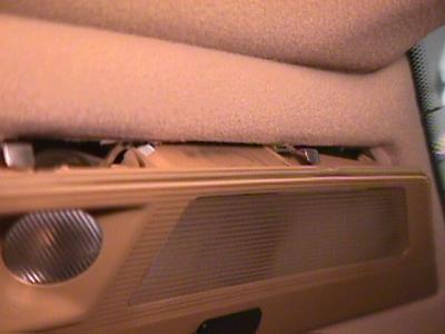
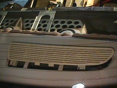
The "package shelf" under the rear window is in two pieces: The speaker shelf in front and the sun screen shelf in back. Both are covered with trim panels.
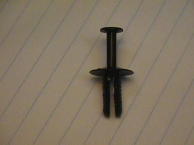
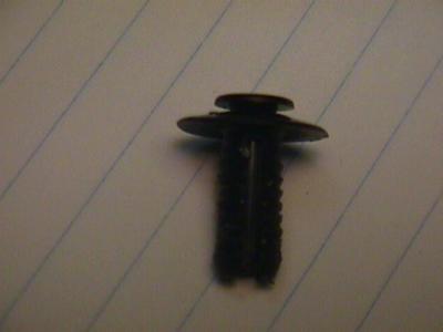
To remove the speaker trim panel, pop out the four plastic "pop" fastners. These fasteners are the kind that contract when you pull out the central pin. (See illustrations below.)
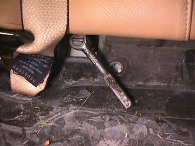
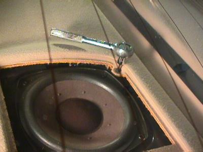
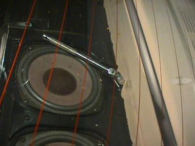
Gently pry up the speaker grills. Remove the two torx-10 screws along the back edge of each speaker. Unfortunatly, there is no room for a normal Torx driver between the rear window and the screw head. You will have to buy a torx socket to fit a small right-angle wrench. (See photo below.) Each screw has a brass washer underneath.
Now you can pull forward and up to remove the speaker time panel.
The speaker shelf itself is a big black plastic casting. There are two large hex-headed screws on the front edge and three machine bolts (13mm socket) along the rear edge.
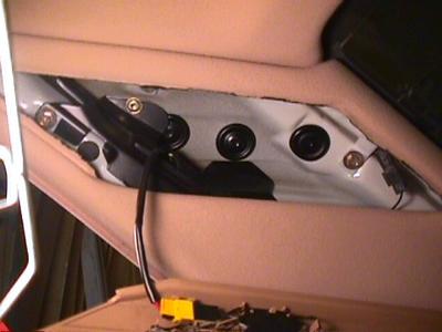
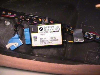
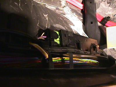
There is a radio (phone? door lock?) device on the driver side with a box attached to the wall. On one end, there is a large connector with a snap-over retaining gate. A single thin coax-wire emerges from the other end and is (somewhat) permanently attached to the speaker shelf. (Maybe the antenna?)
To remove the box, undo the plastic nut and disconnect the large edge connector. (It's the blue thing in the photo below.) Cut the plastic cable tie looped over the coax wire to free the box from the driver-side wall.
Now you can lift and pull forward to partly slide the speaker shelf off the rear deck. It is still attached by large wire bundle on the driver-side rear. This is attached by a large connector block. It has pinch-to-release clips on the edges. I found that I needed to help these a little with a screwdriver while pinching the edges with my other hand.
Now you can remove the whole speaker shelf from the car.
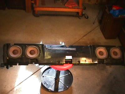
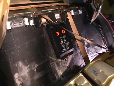
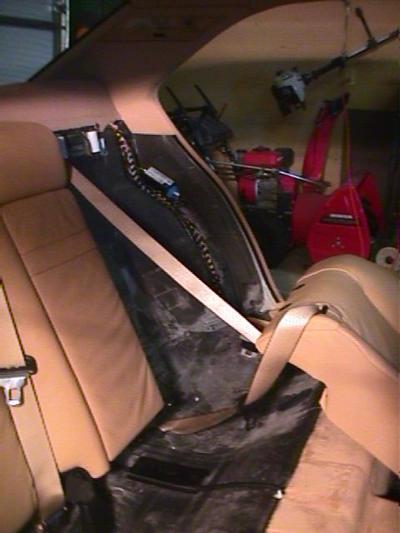
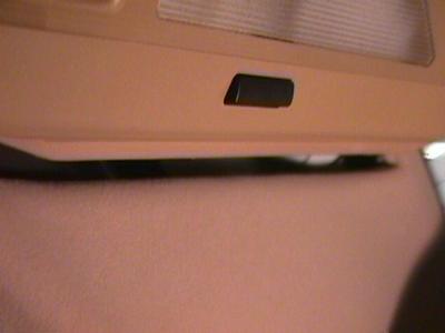
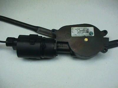
The sun screen mechanism is attached to the underside of the rear trim panel, so they are removed together as a unit.
You don't have to remove the vent covers, but the holes give you something to hold onto when you lift off the sun screen assembly.
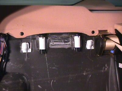
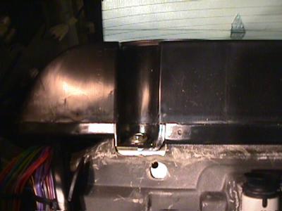
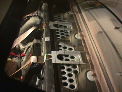
The sun screen and rear shelf are attached from inside the trunk. To remove this assembly, open the trunk and look up at the top surface to see 2 8mm bolts, one 8mm nut and a torx-20 screw. I couldn't get good pictures of these in place, but the photo below shows the fasteners in their relative positions.
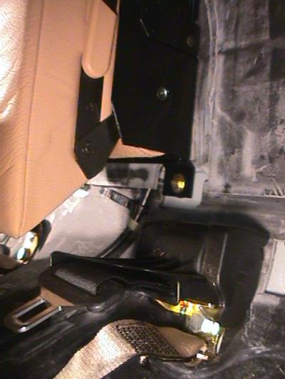
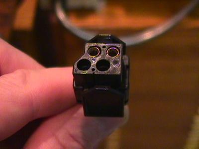
The motor wires are bundled into a cable that goes to a connector block on the passenger-side rear door. On the rear edge of the door frame you will see a green block. There are two separate connectors attached. We want the outer one, which has pinch-release clips.
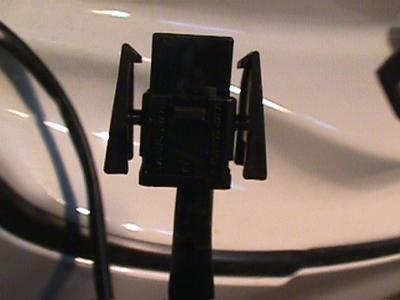
The whole sun screen and rear shelf can now be lifted out of the car.

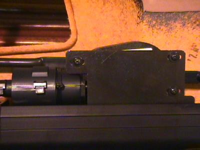
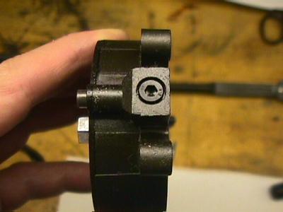
Pry off the spring clips that hold the arms in place out on the cranks.
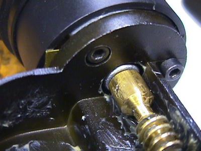
Note the location of the motor mount on the frame before removing.
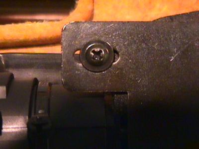
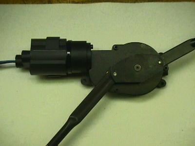
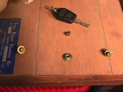
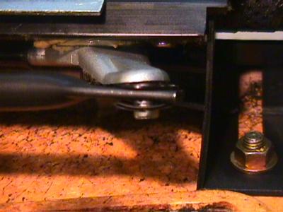
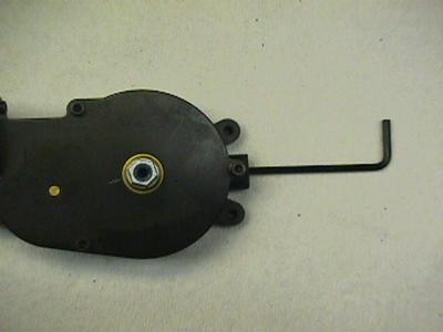
Remove the crank plate screw with a 2.5mm Allen wrench and pry off the plate.
Carefully place a scratch on the lid that lines up with a scratch on the side of the hex-shaped hub. The shade was down (I assume) when you removed the assembly. This mark will be needed when we reassemble the unit.
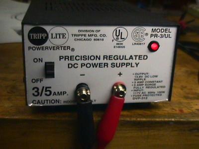
To proceed, you will need a 12 volt D.C. power supply or a small R.V. battery. Test leads with alligator clips on one end work well for the connection.
Using the pins on your test leads, practice operating the gear box using the power supply. By reversing the leads, you can go clockwise (which would lower the screen) or counter-clockwise (which would raise the screen.)
Note: All directions and orientations are with the gear box lid-side up with the motor extending out to the upper left.
Run the gears to an intermediate position between the stops. Now remove the stop screw on the lower right edge.
Rotate the hub clockwise just enough to line up your scratches. Now rotate the hub one full turn counter-clockwise and then 60 degrees more. (60 degrees is one facet on the hex hub, so if your scratch in the middle of a facet, rotate clockwise to the middle of the next facet.)
At this point you have unloaded the large coil spring inside the box. Be sure you have understood and followed the directions closely because you could damage the gears or yourself if you open the box with the gears loaded by the spring.
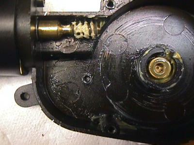
Remove the 3 2.5mm Allen screws that attach the lid. Pry up the lid with a thin blade, working your way around the edge. The lid has to go straight up because of the big brass bearing for the hex hub. Look inside to the right of the hex hub and you will see a smaller shaft and gear. Hold this down in the box with a screwdriver as you pry off the lid. If for some reason, you failed to unload the spring, keeping this gear in place will avoid a run-away.
If all is well, the gears will be loose in the case and you can remove them.
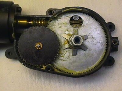
I studied my gears carefully under magnification and couldn't find any serious damage.
I reassemble the gear box without the mainspring and tried running the hub back and forth against the stop screw. As before, it did the "clack-clack-clacks" when it reached the stop on the "down" side (fully clockwise.)
The frequency of the clacking was about 4 Hz. I realized this was much too fast for the brass pinion to be popping in and out of the big pot-metal gear. The noise had to be due to the worm popping out of mesh with the fiber gear.
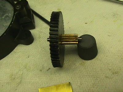
I inspected this gear again and could just make out a small region of slight wear. Could this be enough to disengage the worm under load? If so, the depthing of the worm must be much too shallow. I measured the pitch diameter of the worm and fiber gear and computed the correct center distance. (Yes, it's all in Machinery's Handbook.) Comparing this result to the actual center distance between motor and gear, I found that the mesh was indeed too shallow by almost 0.5mm.
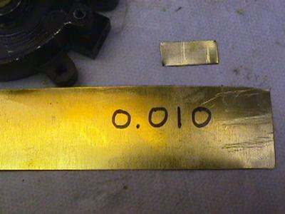
Since the gears were still in good condition, I decided to try moving the motor to obtain a better depth. This turned out to be very easy: I simply put a strip of 0.010" brass shim under the lower edge of the motor. This offset the worm by just the right amount to get a good mesh.
I reassembled the gear box (again) and tried to operate between the stops without the main spring. No clacking!
Install the main spring as shown below.
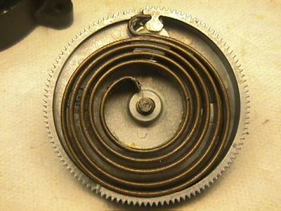
Put the box together and tighten down the lid screws. Remove the stop screw if you have reinstalled it for testing. Rotate clockwise under power just enough to line up your scratch marks. The hub should only have to turn through one or two facets to reallign the marks. Now rotate clockwise one full turn to get the proper load on the spring. The hub now wants to unwind counter-clockwise. This is correct because the hub must turn counter-clockwise to raise the screen. The purpose of the big spring, if you haven't guessed, is to help raise the arms.
Back off in the clockwise direction very slightly so the stop screw can be installed without hitting the stops on the big gear.
Try rotating both ways until you hit the stops. There should be no noise at either end.
Drive the hub clockwise to the stop and back off about 1/2 facet. This is necessary to get the gear case back on the mounting plate with the arms in position.
Reinstall the gear case as show in the earlier pictures. Push the arms over the crack pins and make sure the plastic bearings stay attached to the arms. Put on the spring clips.
Now you're ready to test! Put the whole assembly on the floor with the motor on the bottom side. (As it would be in the car.) Apply power to raise and lower the screen. Woopee.
Reassembling the car takes about one hour. Just follow the steps in reverse.
Good luck with your sun screen!