Figure 347
Hugh Sparks
April 28, 2007
http://www.csparks.com
A relieving attachment (usually for a lathe) is a device for making form-relieved milling cutters. This article describes an unusual implementation that uses gears, rather than ratchets such as those employed by the familiar Balzar "backing-off device" or Ivan Law's Eureka relieving attachment.
The only description of this tool I've found is in William Van Dervort's Modern Machine Shop Tools, copyright 1903 by Norman W. Henley & Company.
Update: I located the patent, see references section below. The inventor's name is Stephen M. Balzer, who is frequently mis-cited as in "Balzar's relieving attachment."
A brief description and illustration appear on pages 241-242 of Van Dervoort's book. I have quoted the section almost verbatim. Mr. Van Dervoort was not into paragraphs, so I have supplied a few to make the otherwise dense explanation easier to read.
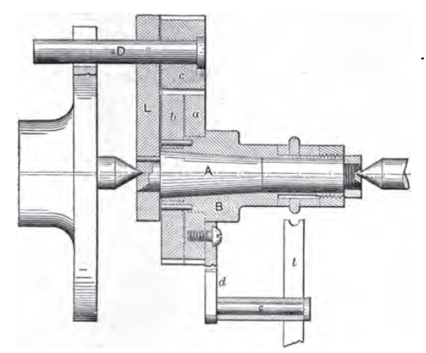
An ingenious lathe attachment for backing off the teeth of milling cutters is shown in Fig. 347. In a device of this character either the tool or the work must be given a slight in-and-out motion for each tooth on the cutter being relieved.
In the case shown, the tool is held in the tool post and advanced to its cut in the ordinary manner. The mandrel A of the attachment has its centers slightly eccentric, the amount of the eccentricity being enough to produce the desired amount of relief on one tooth of the cutter if mounted directly on the mandrel.
The arm L is secured to the mandrel and driven from the face-plate by the carrier D. The sleeve B, which carries the cutter being operated upon, revolves freely upon the mandrel. The gear b is secured to the sleeve and the gear a is loose on the sleeve, and is held from rotating by the arm d which is secured to it and rests upon the top of the tool t. Pinion c is carried loose on the stud D and gears with a and b. Gear b has a smaller number of teeth than a, and as a does not rotate, the rotation of the pinion c around a advances b and the sleeve and cutter a certain fixed amount at each revolution of the mandrel. The geared ratio is such for any given number of teeth in the cutter that the advance per revolution is exactly equal to the circular pitch of the teeth in the cutter. The turning is such as to bring a tooth to the tool when the center of the mandrel is farthest from the tool, thus giving the relief as the tooth advances to the tool.
It is evident from the above that the space between the teeth must be at least equal to the length of the tooth. As this division of space and tooth in relieved milling cutters is not usual, it is necessary to allow the cutter blank to stand still while the mandrel is moving though a part of its revolution. This is accomplished by making the circular pitch of the teeth on about one-half the circumference of b equal to that of the teeth on a and the the teeth on the balance of b of somewhat greater circular pitch. For that portion where the teeth are the same on a and b , the pinion simply turns around both and the sleeve remains stationary. During the balance of the revolution, however, the sleeve will advance an amount equal to the circular pitch of the cutter's tooth.