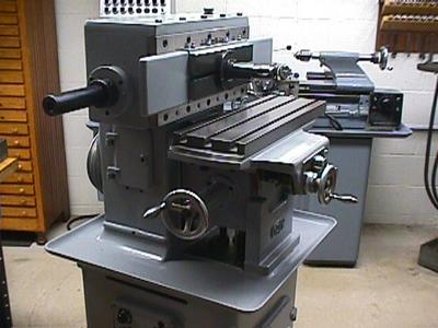
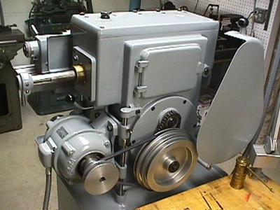
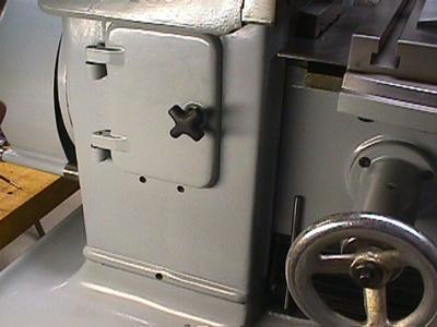
Left side
The Gack works much like an ordinary shaper, but it also has some unique "ram dynamics" controls that I'm still trying to figure out.
Some of these pictures were take while I was assembling the machine, so you will notice a few pieces missing.
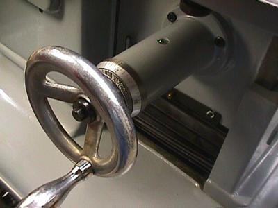
The crank wheel on the left side raises and lowers the table. When planing, this adjusts the depth of cut.
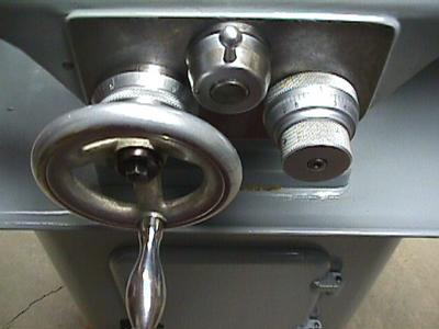
The crank wheel on left side of the front cluster moves the table toward or away from the operator. This is the "feed" axis. When planing a surface, you turn this wheel in small increments during the return stroke to take the next cut.
The lever-knob in the center of the front cluster controls the automatic feed. It has three positions: when straight up as shown, the table must be operated manually with the crank wheel. When turned to the right, the table feeds inward on each stroke. When turned to the left, the table feeds outward on each stroke.
The graduated knob on the right of the front cluster is used to set the feed rate. The frontmost part of the knob is a clutch. It must be loosened to adjust the feed. The rear knurled section is turned to select the feed-per-stroke. After changing the setting, the clutch must be tightend before the machine starts. The entire knob rotates continuously when the machine operates, so these adjustments must be made when the machine is stopped.

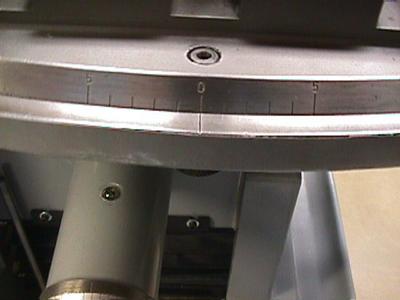
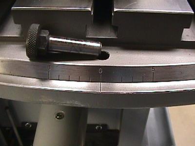
The feed graduations are symmetric around a zero marker. This puzzled me for a while, but it turns out to have a purpose. You want the feed to occur on the return stroke only. When the table is feeding inward, you must use the settings to the right of the zero. When the table is feeding outward, you must use the settings to the left of the zero mark. If you get this wrong, the feed will occur on the cutting stroke.
The table top can pivot to make small angular adjustments. On the left edge of the table, a scale is visible with degree markings. The range of motion is quite a bit larger than the +-5 degrees indicated.
To release the table, clamp bolts must be loosened on the bottom of the table and the zero-set pin must be pulled out from below.
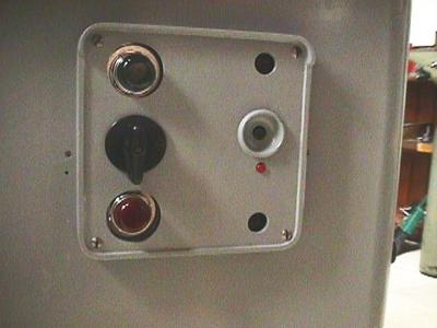
The electrical panel on the left side is very simple. The knob in middle on the left side starts and stops the motor. The green lamp is on when the machine is running. If the overheat solenoid goes off, the red lamp come on. The black button in middle of the right side resets the over-temp solenoid on the motor starter. The small red button below it forces the solenoid to trip.
On rears side you can see the belt cover. You raise this to shift the belt by hand for speed changes.
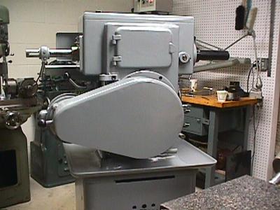
The lever with a black knob right above the motor unlocks the motor mount so it can pivot away from the machine to release the belt tension.
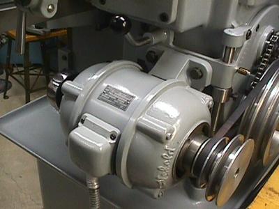
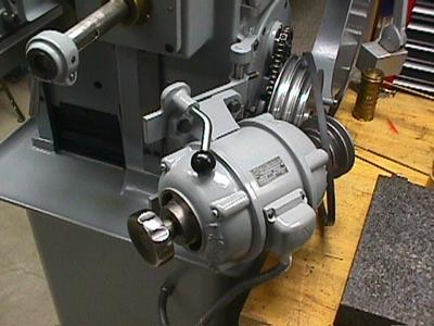
The photo below shows the motor mount opened all the way. The mounting frame slides up and down on the hinge pin. The collar under the upper hinge has a lock bolt. (Not visible in this photo.) When released, you can move the motor up and down to adjust the belt tension.
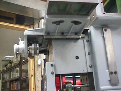
The ram stroke length is adjusted by moving the crank pin. This must be done through a hatch on the left side of the machine.
Rotate the machine using the handwheel on the motor until the adjustment bolts become visible in the hatchway.
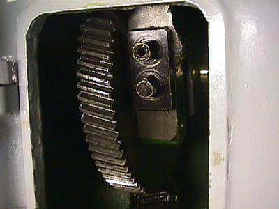
The lower bolt is a lock which must be loosened first. The upper bolt drive a screw that move the crank pivot point on the large bull gear.
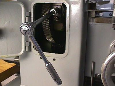
I suppose the machine came with a nifty set of square-headed T-handled sockets. An ordinary 14mm socket works well. It would be nice to have one of those speed cranks.
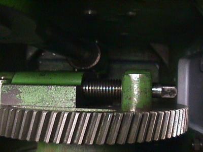
The stop adjustment screws are used to make small adjustments to the angle of the tool when cutting. Normally both screws should be tightened firmly.
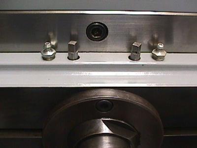
As you can see in the photo, the screws have square heads. On my machine, the heads were drilled through for retaining wire as used on aircraft bolts. Someone must have had a problem with them working loose.
The stop screws are used to rotate and lock in postion a fibre ring inside the spindle housing. This ring (shown in white in the drawing below) has a cutout section. The spindle has a tab that strikes the edges of this cutout.
The entire tool holder is removable and can be replaced in any position on its taper to get a rough adjustment. You would remove and reposition the tool holder when switching between cutting a horizontal surface (tool slot is vertical) and cutting an internal keyway with a boring tool (tool slot is horizontal.) The stops are used only to make fine adjustments.
With your cutting tool in place, rotate the spindle by hand to see how the tool is oriented when cutting. If the angle is wrong, loosen one stop screw and tighten the other. The screw you tighten forces the fibre ring to rotate until it hits the other screw. You need to apply rotational force to the spindle so the tab is against the stop. That way, you can see the effect of your adjustment.
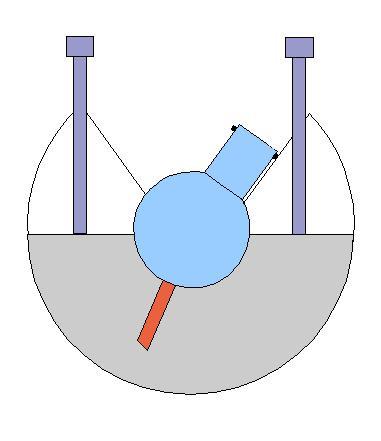
Here is an example: In the figure above, the spindle is against the stop in the cutting position. You can see that the tool is not correctly lined up with the work.
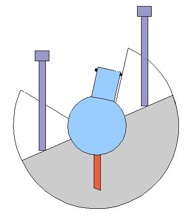
If the tool was this far off, it would be better to remove the tool holder and reposition it on the taper. But as an example, the figure above shows how the stop screws could be adjusted to reposition the fibre ring.
The fibre ring on my machine was stuck to the walls of the spindle housing. The fibre material had aged and oxidized making an effective glue. I ended up taking the whole machine apart to fix this and many other problems.
When you try to move the fibre ring using the stop screws, use only a reasonable amount of force. If the ring is stuck too tightly, you could break apart the laminations. This happened to me and I had to rebond the fibre layers with clamps and epoxy.
Be careful about undoing the stop screws all the way: if your fibre ring is not stuck, you can get it completely out of alignment with the spindle so the screws don't hit the shoulders on the aluminum plate.
Here, I'm on thin ice. Fooling around with these adjustments makes the machine work better but I'm not really sure I understand how they were supposed to work.
The Gack is capable of fairly high speed operation. The ram motion is counter-balanced to some degree by a large reciprocating slide rod that passes completely through the head casting. This rod has rack gear teeth in middle that engage a large pinion on the inside end of the spindle. This pinion drives the spindle rotation. The whole mechanism is quite complex and has several interacting adjustments.
First I'll present how I think this stuff is supposed to work. Then I'll show you the internal mechanism and you can decide if you have a better explanation.
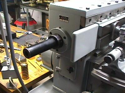
The slide rod brake controls how rapidly and with how much force the spindle rotates (clockwise) back to the cutting position when the ram starts the forward (cutting) stroke. If the brake is set too loose, the spindle won't return to the cutting position at all. If it is set too tight, the spindle will rotate back to the cutting position and hit the stop too violently.
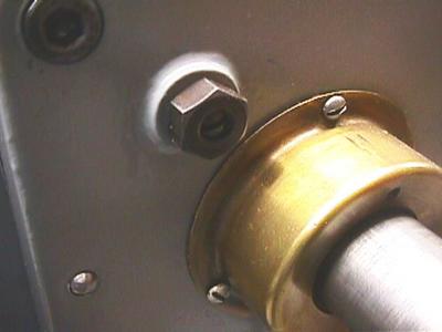
To tighten the brake collet, rotate the black tube clockwise. To loosen the brake collet, rotate it counterclockwise. There is a set screw on the top edge of the brake collet housing. This presses a fibre plug against the brake tube threads. It should be tight enought to prevent the brake tube from unscrewing by itself.
The optimal adjustment depends on the cutting speed and the stroke length. I start the machine and loosen the brake until the spindle doesn't return at all. Then I tighten it until I set it rotate back to the cutting position and hit the stop firmly without a bounce.
When the stroke reaches the end of a cut, the ram retracts to the left. The brake provides some resistance, so the slide rod lags and drives the spindle pinion counter-clockwise rotating the tool out of the work. This action may not be decisive enought to get the tool tip clear of the work when running at high speed. Also, when taking deep cuts, the tool tip may stick in the work at the end of the cut.
To deal with these problems, there is a hook inside the head that grabs the slide rod when it gets to the end of the cutting stroke. The hook holds onto the rod briefly as the ram retracts leftward, forcing the pinion to turn. This gives the spindle a counter-clockwise kick and forces the tool up and out of the work. If you are doing a blind cut up to a shoulder, this action breaks off the chip.
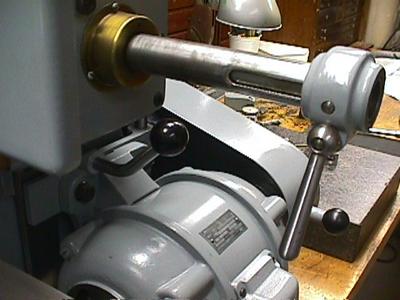
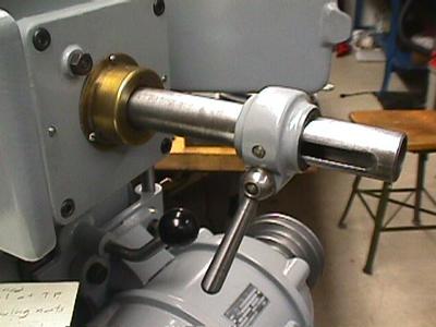
On the right end of the slide rod, you will see a clamping collar. When the lever is released, you can slide this collar back and forth along the rod. This adjusts the position of a sleeve inside the head. The edge of this sleeve gets "grabbed" by the hook at the end of each stroke.
The sleeve position must be adjusted whenever you change the stroke length. You want the hook to catch the rod just as the tool reaches the end of the stroke.
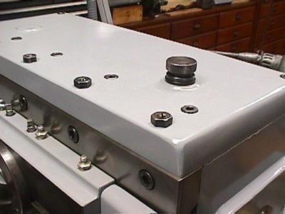
On the right end of the lid, you will see a knurled adjusting knob. This knob control the tension of a spring that pulls the trip hook up against the slide rod. If the tension is too loose, the hook won't act at all. If it is too tight, the hook hammers against the underside of the rod causing excessive wear.
You will see a set screw and lock nut on the upper right of the brass rod bearing cover on the right side. The screw has a leather button on the inside that acts as a bumper and stop for the trip hook. The adjustment should allow the hook to firmly engage the edge of the sleeve without banging the edge of the hook against the sleeve.
There is a similar set screw and bumper adjustment on the underside of the right shoulder of the head. (Not shown.) It is right above the motor mount lock lever. This bumper supports the hook lever when it falls away from the rod after release. The adjustment is not critical as long as it allows the hook to clear the edge of the sleeve. I adjust it to minimize noise.