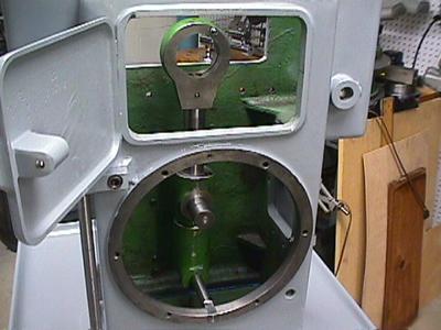
Ram and spindle assembly
The ram oscillates back and forth driven by and adjustable-throw crank.
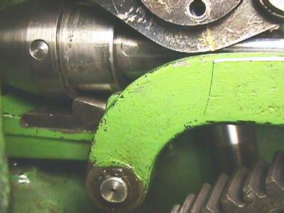
In the photo above, the big journal just to the left of the pinion gets pushed back and forth by the drive lever.
The photo above shows the bearing on the end of the drive lever. The upper edge of the bull gear is visible in the door opening.
The other end of the drive lever rotates on a rocking pivot fixed near the bottom of the machine.
The crank pin slides up and down on the drive lever as it rotates with the bull gear.
The crank pin fits in to the bearing block on the right side of the photo. The threaded hole for the crank throw adjustment is on the lower right.
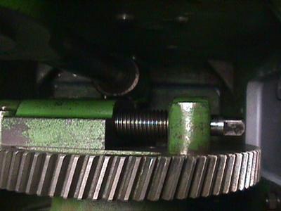
As shown above, the bearing block position on the face of the bull gear can be adjusted radially using a big screw. This changes the crank throw and consequently the stroke length.
This is the mechanism that forces the spindle to "kick up" at the end of the stroke so the tool tip will rapidly clear the work. The main adjustment for this action is the clamping collar on the outside right end of the slide rod. See the operation section of this page for more details.
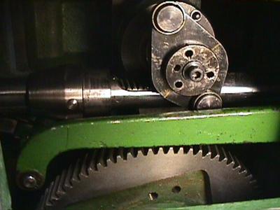
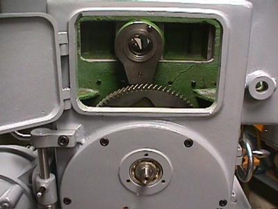
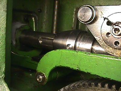
In the photo above, we can see the slide rod with its rack teeth. The spindle pinion is hidden behind the trip cam. Notice that the trip cam has two rollers. The upper roller does nothing in this configuration, but the cam can be removed and replaced so the roller at the longer radius acts on the big green trip arm.
There is a marker on the cam retainer that lines up with marks on the cam body. These positions are labeled with stamped and painted letters. (Hard to see in the photo.) When the short arm of of the cam is active (as shown), the mark points to the letter "K". When the long arm is active, the mark points to the letter "F". Perhaps some German mechanic will write to me and suggest what these letters might indicate.
To take a guess, the roller at a longer radius will act on the trip arm faster because it will press down closer to the pivot on the far right of the head. This would release the hook sooner when the ram starts to retract. How or why this needs to be done I don't know.
The cam retainer bolt is drilled for aircraft-style locking wire. This is not shown in the photo, but I did install this when I started using the machine. If the retaining bolt worked loose, it would fall right down on the bull gear, which would be a disaster.
On the left side of the photo, we can also see the cone-shaped sleeve. This moves left and right when you adjust the clamping coller on the rod end. You can see a shoulder in the middle of the sleeve. This is what gets caught by the hook at the end of the stroke. The grab-hook is not visible, but it is near the left end of the long green arm. It engages the edge of the sleeve from below. The cone-shaped left end of the sleeve pushes the hook out of the way on the cutting stroke.
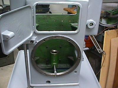
The photo above shows the grab-hook as it engages the lower edge of the sleeve. The hook is part of an arm that is pivoted off to the left outside the view. This lever has bumpers that hit the stops adjusted on the outside of the head casting. The large green lever in the foreground is pivoted at the far right end inside the case. This pivot has a sliding mount to allow the arm to move slightly to the left and right. This is necessary because the left end is pivoted to the hook arm on a solid pin visible in the lower center of the photo.
Looking farther to the left, we can see the grab-hook tension spring. It is adjusted by the knurled knob on top of the lid.
The brake controls the force that returns the spindle to the cutting position as the ram advances from left to right at the beginning of a stroke.
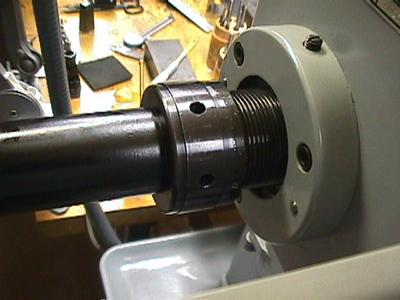
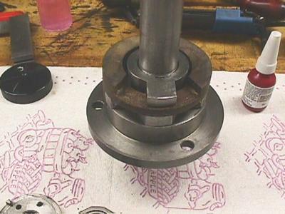
The photo above shows the brake adjustment tube being unscrewed out of the brake housing. On some Gacks, I have seen this glued in place by layers of old paint. This is a major adjustment and needs to be tuned each time you change the stroke length and speed. I have never needed to use a wrench on the spanner holes. Hand tightening is more than enough to secure a good return action.
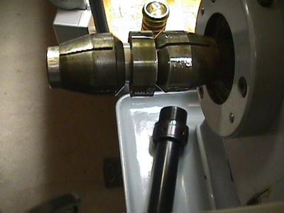
The photo above shows the brake collets with the adjusting sleeve removed. One of my collets has a broken finger. I still haven't gotten around to making a new one. It looks like a tough job.
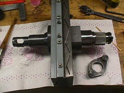
The photo below shows an exploded view of all the spindle components. They are roughly in the order they go on the spindle arbor.
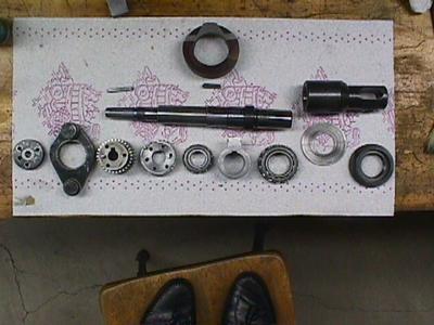
The parts in the bottom row, from left to right:
In the photo, the 4th "ring" from the right in the bottom row of parts is the stop collar. This collar is keyed to the spindle shaft. You can see the keyway groove on the top edge of the hole. The stop itself is the tab that extends up from the collar above the keyway.
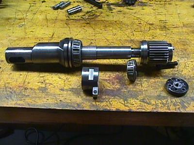
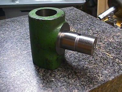
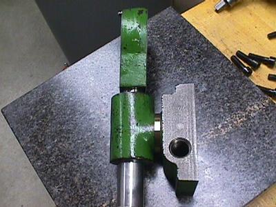
The photo above shows the position of the stop collar next to the partially assembled spindle. You can see a round fibre bumper on the side of the stop collar tab. This reduces vibration and noise when the tab hits the stops.
I had to mill a flat on each side of the collar so I could use a gear puller to get it off the spindle shaft. I think it was heat-shrunk into position. You can see one of the flats on the side of the collar.
The fibre stop ring is locked in position when the machine is running. On each cycle, the tab on the stop collar hits the edges of the cutout in the fibre ring. One edge stops the spindle rotation when cutting, the other edge stops the spindle when it rotates to clear the work on the return stroke.
Below the fibre ring, you can see another aluminum tab. (It is hard to see the details because it is in the shadow of the fibre ring.) This tab is glued and pinned to the fibre ring. It has two shoulders on the left and right sides. The adjustment screws tighten down on these shoulders to lock the fibre ring in place. By differentially adjusting these screws, the tool holder can be rotated through a small range of angles. I believe this is intended to compensate for slight offset in the tool tip caused by grinding without having to remove and reseat the tool holder itself.
A better view of the fibre ring can be seen in the exploded view of the spindle. It is the large ring in the middle at the top of the picture. You can clearly see the shape of the aluminum tab. The stop screws bear down on the horizontal edges on the left and right sides of the tab.